Tina 提供了2种 SPI TFT 显示屏的驱动方式。第一种是官方推荐的 fbdev 方式,使用 Framebuffer implementaion without display hardware of AW 进行 SPI屏幕的驱动。另外一种是使用 fbtft 进行 SPI 屏幕驱动。 fbdev 方式由于 pinctrl 在新内核中调用方式出现修改,所以暂时无法使用。修改难度较大。fbtft 虽然官方wiki表明不建议在 Linux 5.4 中使用,但是其实也是可以使用的,只需要修改一下 GPIO 的注册方式就行。
先驱动 SPI 屏幕
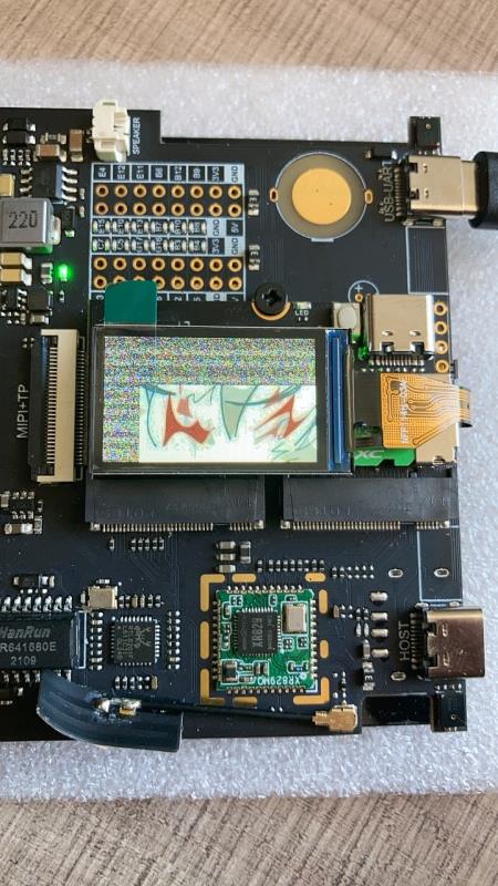
这里驱动的屏幕所选择的是 ST7789V SPI
修改 FBTFT 驱动
进入 tina-d1-open/lichee/linux-5.4/drivers/staging/fbtft 找到 fbtft-core.c
首先加入将要使用到的头文件
#include <linux/gpio.h>
#include <linux/of_gpio.h>
然后找到 static int fbtft_request_one_gpio() 函数,将已经弃用的端口绑定方法改为以下内容
static int fbtft_request_one_gpio(struct fbtft_par *par,
                  const char *name, int index,
                  struct gpio_desc **gpiop)
{
    struct device *dev = par->info->device;
    struct device_node *node = dev->of_node;
    int gpio, flags, ret = 0;
    enum of_gpio_flags of_flags;

    if (of_find_property(node, name, NULL)) {
        gpio = of_get_named_gpio_flags(node, name, index, &of_flags);
        if (gpio == -ENOENT)
            return 0;
        if (gpio == -EPROBE_DEFER)
            return gpio;
        if (gpio < 0) {
            dev_err(dev,
                "failed to get '%s' from DT\n", name);
            return gpio;
        }
        flags = (of_flags & OF_GPIO_ACTIVE_LOW) ? GPIOF_OUT_INIT_LOW :
                            GPIOF_OUT_INIT_HIGH;
        ret = devm_gpio_request_one(dev, gpio, flags,
                        dev->driver->name);
        if (ret) {
            dev_err(dev,
                "gpio_request_one('%s'=%d) failed with %d\n",
                name, gpio, ret);
            return ret;
        }

        *gpiop = gpio_to_desc(gpio);
        fbtft_par_dbg(DEBUG_REQUEST_GPIOS, par, "%s: '%s' = GPIO%d\n",
                            __func__, name, gpio);
    }

    return ret;
}
找到 static void fbtft_reset() 函数,将 RST 信号最后拉高
static void fbtft_reset(struct fbtft_par *par)
{
    if (!par->gpio.reset)
        return;
    fbtft_par_dbg(DEBUG_RESET, par, "%s()\n", __func__);
    gpiod_set_value_cansleep(par->gpio.reset, 1);
    msleep(10);
    gpiod_set_value_cansleep(par->gpio.reset, 0);
    msleep(200);
    gpiod_set_value_cansleep(par->gpio.reset, 1);
    msleep(10);
}
找到 static void fbtft_set_addr_win() 函数,添加地址偏移。否则会出现下图部分雪花屏现象。
static void fbtft_set_addr_win(struct fbtft_par *par, int xs, int ys, int xe,
			       int ye)
{
	switch(par->info->var.rotate)
	{
		case   0: xs+=53;xe+=53;ys+=40;ye+=40;
				 break;
		case  90: xs+=40;xe+=40;ys+=53;ye+=53;
				 break;
		case 180: xs+=53;xe+=53;ys+=40;ye+=40;
				 break;
		case 270: xs+=40;xe+=40;ys+=53;ye+=53;
				 break;
		default :
				 break;
	}

	write_reg(par, MIPI_DCS_SET_COLUMN_ADDRESS,
		  (xs >> 8) & 0xFF, xs & 0xFF, (xe >> 8) & 0xFF, xe & 0xFF);

	write_reg(par, MIPI_DCS_SET_PAGE_ADDRESS,
		  (ys >> 8) & 0xFF, ys & 0xFF, (ye >> 8) & 0xFF, ye & 0xFF);

	write_reg(par, MIPI_DCS_WRITE_MEMORY_START);
}
找到 fb_st7789v.c,参照STM32的初始化函数对初始化部分进行修改。
static int init_display(struct fbtft_par *par)
{
    par->fbtftops.reset(par);
    mdelay(50);
    write_reg(par,0x36,0x00);
    write_reg(par,0x3A,0x05);
    write_reg(par,0xB2,0x0C,0x0C,0x00,0x33,0x33);
    write_reg(par,0xB7,0x35);
    write_reg(par,0xBB,0x19);
    write_reg(par,0xC0,0x2C);
    write_reg(par,0xC2,0x01);
    write_reg(par,0xC3,0x12);
    write_reg(par,0xC4,0x20);
    write_reg(par,0xC6,0x0F);
    write_reg(par,0xD0,0xA4,0xA1);
    write_reg(par,0xE0,0xD0,0x04,0x0D,0x11,0x13,0x2B,0x3F,0x54,0x4C,0x18,0x0D,0x0B,0x1F,0x23);
    write_reg(par,0xE1,0xD0,0x04,0x0C,0x11,0x13,0x2C,0x3F,0x44,0x51,0x2F,0x1F,0x1F,0x20,0x23);
    write_reg(par,0x21);
    write_reg(par,0x11);
    mdelay(50);
    write_reg(par,0x29);
    mdelay(200);
    return 0;
}
将屏幕大小配置为屏幕实际大小
static struct fbtft_display display = {
	.regwidth = 8,
	.width = 135,
	.height = 240,
	.gamma_num = 2,
	.gamma_len = 14,
	.gamma = DEFAULT_GAMMA,
	.fbtftops = {
		.init_display = init_display,
		.set_var = set_var,
		.set_gamma = set_gamma,
		.blank = blank,
	},
};
设备树修改
首先打开电路图,找到 SPI 屏幕的电路。
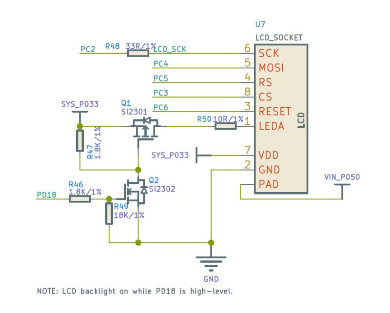
根据电路,找到 pio 节点,添加 SPI0 所用引脚,spi0_pins_a 作为数据时钟绑定,spi0_pins_b 作为 CS 的绑定,并上拉。RST,DC,背光在这里不做声明。
spi0_pins_a: spi0@0 {
	pins = "PC2", "PC4";
	function = "spi0";
	drive-strength = <10>;
};

spi0_pins_b: spi0@1 {
	pins = "PC3";
	function = "spi0";
	drive-strength = <10>;
	bias-pull-up;
};
然后找到 SPI0 节点,添加屏幕使用的设备树。使用 pinctrl-0 将 pio 中定义的 SPI 引脚进行注册。RST,DC,背光在这里进行绑定,并设置其工作电平。
&spi0 {
	clock-frequency = <100000000>;
	pinctrl-0 = <&spi0_pins_a &spi0_pins_b>;
	status = "okay";

    st7789v@0 {
    	status = "okay";
    	compatible = "sitronix,st7789v";
        reg = <0>;
        spi-max-frequency = <32000000>;
        rotate = <90>;
        rgb;
        fps = <30>;
        buswidth = <8>;
		reset = <&pio PC 6 GPIO_ACTIVE_LOW>;
	    dc = <&pio PC 5 GPIO_ACTIVE_LOW>;
		led = <&pio PD 18 GPIO_ACTIVE_HIGH>;
        debug = <1>;
    };
};
最后,将不需要的屏幕关闭,方便调试
&disp {
	disp_init_enable = <0>;
    ......
}

&lcd0 {
	lcd_used = <0>;
    ......
}

&hdmi {
	hdmi_used = <0>;
    ......
}
内核配置
进入 kernel_menuconfig ,开启 FBTFT,关闭 RGB,MIPI 所使用的 DISP Driver Support(sunxi-disp2) 输出。
Device Drivers  --->
	 Graphics support  --->
	 	Frame buffer Devices  --->
	 		 <*> Support for frame buffer devices  --->
	 		 Video support for sunxi  --->
	 		 	 < > DISP Driver Support(sunxi-disp2)
	 [*] Staging drivers  --->
	 	 <*>   Support for small TFT LCD display modules  --->
	 	 	  <*>   FB driver for the ST7789V LCD Controller
由于上面配置关闭了 DISP Driver Support(sunxi-disp2) ,所用需要在 menuconfig 里将内核模块关闭,否则会出现找不到驱动的错误。
Kernel modules  --->
	Video Support  --->
		 < > kmod-sunxi-disp....................................... sunxi-disp support
         < > kmod-sunxi-g2d......................................... sunxi-g2d support
         < > kmod-sunxi-hdmi....................................... sunxi-hdmi support
         < > kmod-sunxi-uvc......................................... sunxi-uvc support
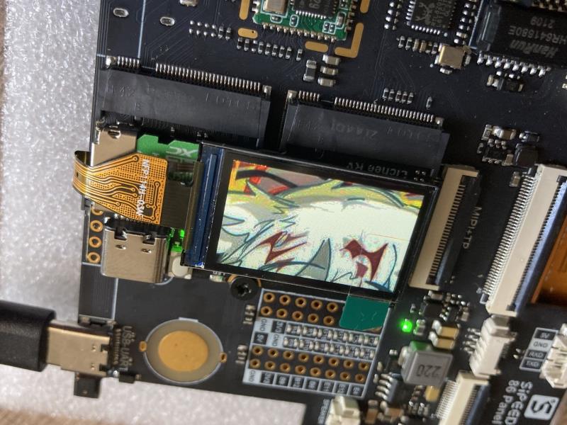
编译,打包,使用 fbviewer 进行测试
make -j65535
pack

fbviewer Yuzuki.jpg
修改为双屏驱动
修改双屏也很简单,SPI 屏幕调试完成之后,将刚才关闭的各类驱动打开即可。
配置设备树
找到 SPI0 节点,将背光 led 注释掉,查看电路图可知 RGB 屏幕和 SPI 屏幕使用的背光是同一个,这里不需要分开注册。
&spi0 {
	clock-frequency = <100000000>;
	pinctrl-0 = <&spi0_pins_a &spi0_pins_b>;
	status = "okay";

    st7789v@0 {
    	status = "okay";
    	compatible = "sitronix,st7789v";
        reg = <0>;
        spi-max-frequency = <32000000>;
        rotate = <90>;
        rgb;
        fps = <30>;
        buswidth = <8>;
		reset = <&pio PC 6 GPIO_ACTIVE_LOW>;
	    dc = <&pio PC 5 GPIO_ACTIVE_LOW>;
//		led = <&pio PD 18 GPIO_ACTIVE_HIGH>;
        debug = <1>;
    };
};
把之前关闭的显示输出重新打开
&disp {
	disp_init_enable = <1>;
    ......
}

&lcd0 {
	lcd_used = <1>;
    ......
}

&hdmi {
	hdmi_used = <1>;
    ......
}
配置内核
进入 kernel_menuconfig ,开启 DISP Driver Support(sunxi-disp2) 输出,并选择面板驱动。
Device Drivers  --->
	 Graphics support  --->
	 	Frame buffer Devices  --->
	 		 <*> Support for frame buffer devices  --->
	 		 Video support for sunxi  --->
	 		 	 <*> DISP Driver Support(sunxi-disp2)
	 		 	 <*> HDMI2.0 Driver Support(sunxi-disp2)
	 		 	 	 HDMI2.0 PHY SELECT. (Allwinner PHY)  --->
	 		 	     LCD panels select  --->
	 		 	 		 [*] LCD support ST7701S RGB panel
	 [*] Staging drivers  --->
	 	 <*>   Support for small TFT LCD display modules  --->
	 	 	  <*>   FB driver for the ST7789V LCD Controller
在 menuconfig 里将内核模块重新打开。
Kernel modules  --->
	Video Support  --->
		 <*> kmod-sunxi-disp....................................... sunxi-disp support
         <*> kmod-sunxi-g2d......................................... sunxi-g2d support
         <*> kmod-sunxi-hdmi....................................... sunxi-hdmi support
         <*> kmod-sunxi-uvc......................................... sunxi-uvc support
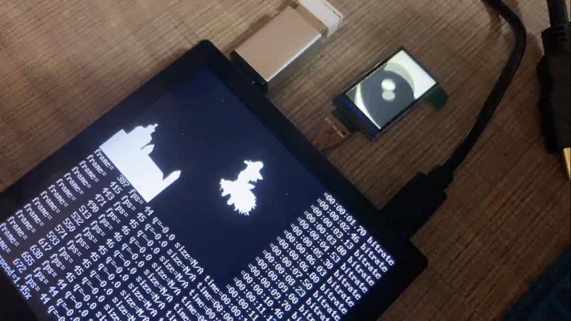
编译,打包,测试。这里使用 ffmpeg 进行双屏播放 badapple.mp4
附录:部分设备树完整参考(配置双屏后,HDMI禁用了)
&pio {
...前略...
spdif_pins_b: spdif_sleep@0 {
pins = "PB0";
function = "io_disabled";
drive-strength = <20>;
bias-disable;
};
spi0_pins_a: spi0@0 {
pins = "PC2", "PC4"; /*clk mosi*/
function = "spi0";
drive-strength = <10>;
};
spi0_pins_b: spi0@1 {
pins = "PC3";
function = "spi0";
drive-strength = <10>;
bias-pull-up; // only CS should be pulled up
};
spi1_pins_a: spi1@0 {
pins = "PD11", "PD12", "PD13","PD14", "PD15"; /*clk mosi miso hold wp*/
function = "spi1";
drive-strength = <10>;
};
spi1_pins_b: spi1@1 {
pins = "PD10";
function = "spi1";
drive-strength = <10>;
bias-pull-up; // only CS should be pulled up
};
spi1_pins_c: spi1@2 {
pins = "PD10", "PD11", "PD12", "PD13","PD14", "PD15";
function = "gpio_in";
drive-strength = <10>;
};
ledc_pins_a: ledc@0 {
pins = "PC0";
function = "ledc";
drive-strength = <10>;
};
ledc_pins_b: ledc@1 {
pins = "PC0";
function = "gpio_in";
};
...后略...
};
&spi0 {
clock-frequency = <100000000>;
pinctrl-0 = <&spi0_pins_a &spi0_pins_b>;
status = "okay";
st7789v@0 {
status = "okay";
compatible = "sitronix,st7789v";
reg = <0>;
spi-max-frequency = <32000000>;
rotate = <90>;
rgb;
fps = <30>;
buswidth = <8>;
reset = <&pio PC 6 GPIO_ACTIVE_LOW>;
dc = <&pio PC 5 GPIO_ACTIVE_LOW>;
// led = <&pio PD 18 GPIO_ACTIVE_HIGH>;
debug = <1>;
};
};
/*----------------------------------------------------------------------------------
disp init configuration
disp_mode (0:screen0<screen0,fb0>)
screenx_output_type (0:none; 1:lcd; 2:tv; 3:hdmi;5:vdpo)
screenx_output_mode (used for hdmi output, 0:480i 1:576i 2:480p 3:576p 4:720p50)
(5:720p60 6:1080i50 7:1080i60 8:1080p24 9:1080p50 10:1080p60)
screenx_output_format (for hdmi, 0:RGB 1:yuv444 2:yuv422 3:yuv420)
screenx_output_bits (for hdmi, 0:8bit 1:10bit 2:12bit 2:16bit)
screenx_output_eotf (for hdmi, 0:reserve 4:SDR 16:HDR10 18:HLG)
screenx_output_cs (for hdmi, 0:undefined 257:BT709 260:BT601 263:BT2020)
screenx_output_dvi_hdmi (for hdmi, 0:undefined 1:dvi mode 2:hdmi mode)
screen0_output_range (for hdmi, 0:default 1:full 2:limited)
screen0_output_scan (for hdmi, 0:no data 1:overscan 2:underscan)
screen0_output_aspect_ratio (for hdmi, 8-same as original picture 9-4:3 10-16:9 11-14:9)
fbx format (4:RGB655 5:RGB565 6:RGB556 7:ARGB1555 8:RGBA5551 9:RGB888 10:ARGB8888 12:ARGB4444)
fbx pixel sequence (0:ARGB 1:BGRA 2:ABGR 3:RGBA)
fb0_scaler_mode_enable(scaler mode enable, used FE)
fbx_width,fbx_height (framebuffer horizontal/vertical pixels, fix to output resolution while equal 0)
lcdx_backlight (lcd init backlight,the range:[0,256],default:197
lcdx_yy (lcd init screen bright/contrast/saturation/hue, value:0~100, default:50/50/57/50)
lcd0_contrast (LCD contrast, 0~100)
lcd0_saturation (LCD saturation, 0~100)
lcd0_hue (LCD hue, 0~100)
framebuffer software rotation setting:
disp_rotation_used: (0:disable; 1:enable,you must set fbX_width to lcd_y,
set fbX_height to lcd_x)
degreeX: (X:screen index; 0:0 degree; 1:90 degree; 3:270 degree)
degreeX_Y: (X:screen index; Y:layer index 0~15; 0:0 degree; 1:90 degree; 3:270 degree)
devX_output_type : config output type in bootGUI framework in UBOOT-2018.
(0:none; 1:lcd; 2:tv; 4:hdmi;)
devX_output_mode : config output resolution(see include/video/sunxi_display2.h) of bootGUI framework in UBOOT-2018
devX_screen_id : config display index of bootGUI framework in UBOOT-2018
devX_do_hpd : whether do hpd detectation or not in UBOOT-2018
chn_cfg_mode : Hardware DE channel allocation config. 0:single display with 6
channel, 1:dual display with 4 channel in main display and 2 channel in second
display, 2:dual display with 3 channel in main display and 3 channel in second
in display.
----------------------------------------------------------------------------------*/
&disp {
disp_init_enable = <1>;
disp_mode = <0>;
screen0_output_type = <1>;
screen0_output_mode = <4>;
screen1_output_type = <3>;
screen1_output_mode = <10>;
screen1_output_format = <0>;
screen1_output_bits = <0>;
screen1_output_eotf = <4>;
screen1_output_cs = <257>;
screen1_output_dvi_hdmi = <2>;
screen1_output_range = <2>;
screen1_output_scan = <0>;
screen1_output_aspect_ratio = <8>;
dev0_output_type = <1>;
dev0_output_mode = <4>;
dev0_screen_id = <0>;
dev0_do_hpd = <0>;
dev1_output_type = <4>;
dev1_output_mode = <10>;
dev1_screen_id = <1>;
dev1_do_hpd = <1>;
def_output_dev = <0>;
hdmi_mode_check = <1>;
fb0_format = <0>;
fb0_width = <0>;
fb0_height = <0>;
fb1_format = <0>;
fb1_width = <0>;
fb1_height = <0>;
chn_cfg_mode = <1>;
disp_para_zone = <1>;
/*VCC-LCD*/
/* dc1sw-supply = <®_dc1sw>;*/
/*VCC-DSI*/
/* eldo3-supply = <®_eldo3>;*/
/*VCC-PD*/
/* dcdc1-supply = <®_dcdc1>;*/
};
/*----------------------------------------------------------------------------------
;lcd0 configuration
;lcd_if: 0:hv(sync+de); 1:8080; 2:ttl; 3:lvds; 4:dsi; 5:edp; 6:extend dsi
;lcd_hv_if 0:Parallel RGB; 8:Serial RGB; 10:Dummy RGB; 11: RGB Dummy;12:CCIR656
;lcd_hv_clk_phase 0:0 degree;1:90 degree;2:180 degree;3:270 degree
;lcd_hv_sync_polarity 0:vs low,hs low; 1:vs high,hslow; 2:vs low,hs high; 3:vs high,hs high
;lcd_hv_syuv_seq 0:YUYV; 1:YVYU; 2:UYVY; 3:VYUY
;lcd_cpu_if 0:18bit/1 cycle parallel(RGB666); 4:16bit/1cycle parallel (RGB565)
; 6:18bit/3 cycle parallel(RGB666); 7:16bit/2cycle parallel (RGB565)
;lcd_cpu_te 0:frame auto trigger; 1:frame triggered by te rising edge; 2:frame triggered by te falling edge;
;lcd_dsi_if 0:video mode; 1: Command mode; 2:video burst mode
;lcd_dsi_te 0:frame auto trigger; 1:frame triggered by te rising edge; 2:frame triggered by te falling edge;
;lcd_x: lcd horizontal resolution
;lcd_y: lcd vertical resolution
;lcd_width: width of lcd in mm
;lcd_height: height of lcd in mm
;lcd_dclk_freq: in MHZ unit
;lcd_pwm_freq: in HZ unit
;lcd_pwm_pol: lcd backlight PWM polarity
;lcd_pwm_max_limit lcd backlight PWM max limit(<=255)
;lcd_hbp: hsync back porch(pixel) + hsync plus width(pixel);
;lcd_ht: hsync total cycle(pixel)
;lcd_vbp: vsync back porch(line) + vysnc plus width(line)
;lcd_vt: vysnc total cycle(line)
;lcd_hspw: hsync plus width(pixel)
;lcd_vspw: vysnc plus width(pixel)
;lcd_lvds_if: 0:single link; 1:dual link
;lcd_lvds_colordepth: 0:8bit; 1:6bit
;lcd_lvds_mode: 0:NS mode; 1:JEIDA mode
;lcd_frm: 0:disable; 1:enable rgb666 dither; 2:enable rgb656 dither
;lcd_io_phase: 0:noraml; 1:intert phase(0~3bit: vsync phase; 4~7bit:hsync phase;
; 8~11bit:dclk phase; 12~15bit:de phase)
;lcd_gamma_en lcd gamma correction enable
;lcd_bright_curve_en lcd bright curve correction enable
;lcd_cmap_en lcd color map function enable
;deu_mode 0:smoll lcd screen; 1:large lcd screen(larger than 10inch)
;lcdgamma4iep: Smart Backlight parameter, lcd gamma vale * 10;
; decrease it while lcd is not bright enough; increase while lcd is too bright
;smart_color 90:normal lcd screen 65:retina lcd screen(9.7inch)
;Pin setting for special function ie.LVDS, RGB data or vsync
; name(donot care) = port:PD12<pin function><pull up or pull down><drive ability><output level>
;Pin setting for gpio:
; lcd_gpio_X = port:PD12<pin function><pull up or pull down><drive ability><output level>
;Pin setting for backlight enable pin
; lcd_bl_en = port:PD12<pin function><pull up or pull down><drive ability><output level>
;fsync setting, pulse to csi
;lcd_fsync_en (0:disable fsync,1:enable)
;lcd_fsync_act_time (active time of fsync, unit:pixel)
;lcd_fsync_dis_time (disactive time of fsync, unit:pixel)
;lcd_fsync_pol (0:positive;1:negative)
;gpio config: <&pio for cpu or &r_pio for cpus, port, port num, pio function,
pull up or pull down(default 0), driver level(default 1), data>
;For dual link lvds: use lvds2link_pins_a and lvds2link_pins_b instead
;For rgb24: use rgb24_pins_a and rgb24_pins_b instead
;For lvds1: use lvds1_pins_a and lvds1_pins_b instead
;For lvds0: use lvds0_pins_a and lvds0_pins_b instead
;----------------------------------------------------------------------------------*/
&lcd0 {
lcd_used = <1>;
lcd_driver_name = "st7701s_rgb";
lcd_if = <0>;
lcd_hv_if = <0>;
lcd_width = <70>;
lcd_height = <72>;
lcd_x = <480>;
lcd_y = <480>;
lcd_dclk_freq = <19>;
lcd_hbp = <60>;
lcd_ht = <612>;
lcd_hspw = <12>;
lcd_vbp = <18>;
lcd_vt = <520>;
lcd_vspw = <4>;
lcd_backlight = <50>;
lcd_pwm_used = <1>;
lcd_pwm_ch = <7>;
lcd_pwm_freq = <20000>;
lcd_pwm_pol = <1>;
lcd_bright_curve_en = <0>;
lcd_frm = <1>;
lcd_io_phase = <0x0000>;
lcd_gamma_en = <0>;
lcd_cmap_en = <0>;
lcd_hv_clk_phase= <0>;
lcd_hv_sync_polarity= <0>;
lcd_rb_swap = <0>;
lcd_power = "vcc-lcd";
lcd_pin_power = "vcc-pd";
lcd_gpio_0 = <&pio PG 13 GPIO_ACTIVE_HIGH>;
lcd_gpio_1 = <&pio PE 14 GPIO_ACTIVE_HIGH>;
lcd_gpio_2 = <&pio PE 12 GPIO_ACTIVE_HIGH>;
lcd_gpio_3 = <&pio PE 15 GPIO_ACTIVE_HIGH>;
pinctrl-0 = <&rgb18_pins_a>;
pinctrl-1 = <&rgb18_pins_b>;
};
&hdmi {
hdmi_used = <0>;
hdmi_power_cnt = <0>;
hdmi_cts_compatibility = <1>;
hdmi_hdcp_enable = <1>;
hdmi_hdcp22_enable = <0>;
hdmi_cec_support = <1>;
hdmi_cec_super_standby = <0>;
ddc_en_io_ctrl = <0>;
power_io_ctrl = <0>;
};